Class D.
FITTINGS, MATERIALS AND DETAILS OF CONSTRUCTION.
(Light, Power and Heat. For Signaling Systems, see Class E.)
ALL SYSTEMS AND VOLTAGES.
The following rules are but a partial outline of requirements. Devices or materials which fulfill the conditions of these requirements and no more, will not necessarily be acceptable. All fittings and materials should be submitted for examination and test before being introduced for use.
Insulated Wires—Rules 40 to 48
40. General Rules.
a. Copper for insulated conductors must never vary in diameter so as to be more than two one-thousandths of an inch less than the specified size.
b. Wires and cables of all kinds designed to meet the following specifications must have a distinctive marking the entire length of the coil so that they may be readily identified in the field. They must also be plainly tagged or marked as follows:—
- The maximum voltage at which the wire is designed to be used.
- The words "National Electrical Code Standard."
- Name of the manufacturing company and, if desired, trade name of the wire.
- Month and year when manufactured.
41. Rubber-Covered Wire.
a. Copper for conductors must be thoroughly tinned.
Insulation for Voltages between 0 and 600.
b. Must be of rubber or other approved substance, and of a thickness not less than that given in the following table:—
| B. & S. Gage. | Thickness |
|---|---|
| 18 to 16 | 1-32 inch. |
| 15 to 8 | 3-64 " |
| 7 to 2 | 1-16 " |
| 1 to 0000 | 5-64 " |
| Circular Mils. | |
| 250,000 to 500,000 | 3-32 " |
| 500,000 to 1,000,000 | 7-64 " |
| Over 1,000,000 | 1-8 " |
c. The completed coverings must show an insulation resistance of at least 100 megohms per mile during thirty days' immersion in water at seventy degrees Fahrenheit.
d. Each foot of the completed covering must show a dielectric strength sufficient to resist throughout five minutes the application of an electro-motive force proportionate to the thickness of insulation in accordance with the following table:—
| THICKNESS in 64ths inches | BREAKDOWN TEST on 1 foot |
|---|---|
| 1 | 3,000 Volts A. C. |
| 2 | 6,000 " " |
| 3 | 9,000 " " |
| 4 | 11,000 " " |
| 5 | 13,000 " " |
| 6 | 15,000 " " |
| 7 | 16,500 " " |
| 8 | 18,000 " " |
| 10 | 21,000 " " |
| 12 | 23,500 " " |
| 14 | 26,000 " " |
| 16 | 28,000 " " |
The source of alternating electro-motive force shall be a transformer of at least one kilowatt capacity. The application of the electro-motive force shall first be made at 4,000 volts for five minutes and then the voltage increased by steps of not over 3,000 volts, each held for five minutes, until the rupture of the insulation occurs. The tests for dielectric strength shall be made on a sample of wire which has been immersed in water for seventy-two hours. One foot of the wire under test is to be submerged in a conducting liquid held in a metal trough, one of the transformer terminals being connected to the copper of the wire and the other to the metal of the trough.
Insulations for Voltages between 600 and 3,500.
e. The thickness of the insulating wall must not be less than that given in the following table:—
| B. & S. Gage. | Thickness. |
|---|---|
| 14 to 1 | 3-32 inch. |
| 0 to 0000 | 3-32 " covered by tape or braid |
| Circular Mils. | |
| 250,000 to 500,000 | 3-32 " " " " |
| Over 500,000 | 1-8 " " " " |
| f. The requirements as to insulation and breakdown resistance for wires for low-potential systems shall apply, with the exception that an insulation resistance of not less than 300 megohms per mile shall be required. |
Insulations for Voltages over 3,500.
g. Wire for arc-light circuits exceeding 3,500 volts potential must have an insulating wall not less than three-sixteenths of an inch in thickness, and shall withstand a breakdown test of at least 23,500 volts and have an insulation of at least 500 megohms per mile. The tests on this wire to be made under the same conditions as for low-potential wires.
Protecting Braid.
h. All of the above insulations must be protected by a substantial braided covering, properly saturated with a preservative compound. This covering must be sufficiently strong to withstand all the abrasion likely to be met with in practice, and sufficiently elastic to permit all wires smaller than No. 7 B. & S. gage to be bent around a cylinder with twice the diameter of wire, without injury to the braid.
42. Slow-burning Weatherproof Wire.
a. The insulation must consist of two coatings, one to be fireproof in character and the other to be weatherproof. The fireproof coating must be on the outside and must comprise about 6-10 of the total thickness of the wall. The completed covering must be of a thickness not less than that given in the following table:—
| B. & S. Gage. | Thickness. |
|---|---|
| 14 to 8 | 3-64 inch. |
| 7 to 2 | 1-16 " |
| 1 to 0000 | 5-64 " |
| Circular Mils | |
| 250,000 to 500,000 | 3-32 " |
| 500,000 to 1,000,000 | 7-64 " |
| Over 1,000,000 | 1-8 " |
b. The fireproof coating shall be of the same kind as that required for "slow-burning wire," and must be finished with a hard, smooth surface if it is on the outside.
c. The weatherproof coating shall consist of a stout braid, applied and treated as required for "weatherproof wire," and must be thoroughly slicked down if it is on the outside.
43. Slow-burning Wire.
a. The cotton or insulation must consist of layers of cotton or other thread, all the interstices of which must be filled with the fireproofing compound, or of material having equivalent fire resisting and insulating properties. The outer layer must be braided and specially designed to withstand abrasion. The thickness of insulation must not be less than that required for "Slow-Burning Weatherproof Wire," and the outer surface must be finished smooth and hard.
44. Weatherproof Wire.
a. The insulating covering shall consist of at least three braids, all of which must be thoroughly saturated with a dense moisture-proof compound, applied in such a manner as to drive any atmospheric moisture from the cotton braiding, thereby securing a covering to a great degree waterproof and of high insulating power. This compound must retain its elasticity at 0 deg. Fahr. and must not drip at 160 deg. Fahr. The thickness of insulation must not be less than that required for "slow-burning weatherproof wire," and the outer surface must be thoroughly slicked down.
45. Flexible Cord.
(For installation rules, see No. 28.)
a. Must, except as required for portable heating apparatus (see section g), be made of stranded copper conductors, each strand to be not larger than No. 26 or smaller than No. 30 B. & S. gage, and each stranded conductor must be covered by an approved insulation and protected from mechanical injury by a tough, braided outer covering.
For Pendant Lamps.
b. Each stranded conductor must have a carrying capacity equivalent to not less than a No. 18 B. & S. gage wire.
c. The covering of each stranded conductor must be made up as follows:—
- A tight, close wind of fine cotton.
- The insulation proper, which shall be waterproof.
- An outer cover of silk or cotton.
d. The insulation must be solid, at least one thirty-second of an inch thick, and must show an insulation resistance of fifty megohms per mile throughout two weeks' immersion in water at 70 degrees Fahrenheit, and stand the tests prescribed for low-tension wires as far as they apply.
e. The outer protecting braiding should be so put on and sealed in place that when cut it will not fray out, and where cotton is used, it should be impregnated with a flameproof paint, which will not have an injurious effect on the insulation.
For Portables.
f. Flexible cord for portable use must meet all of the requirements for flexible cord "for pendant lamps," both as to construction and thickness of insulation, and in addition must have a tough braided cover over the whole. There must also be an extra layer of rubber between the outer cover and the flexible cord, and in moist places the outer cover must be saturated with a moisture-proof compound, thoroughly slicked down, as required for "weatherproof wire" in No. 44. In offices, dwellings or in similar places where the appearance is an essential feature, a silk cover may be substituted for the weatherproof braid.
For Portable Heating Apparatus.
g. Must be made up as follows:—
- Conductors must be of braided copper, each strand not to be larger than No. 30 or smaller than No. 36 B. &. S. gage.
- An insulating covering of rubber or other approved material not less than one sixty-fourth inch in thickness.
- A braided covering not less than one thirty-second inch thick, composed of best quality long fibre asbestos, containing not over 5 per cent of vegetable fibre.
- The several conductors comprising the cord to be enclosed by an outer reinforcing covering not less than one sixty-fourth inch thick, especially designed to resist abrasion, and so treated as to prevent the cover from fraying.
46. Fixture Wire.
(For installation rules, see No. 24 v to y.)
a. May be made of solid or stranded conductors with no strands smaller than No. 30 B. & S. gage and must have a carrying capacity not less than that of a No. 18 B. & S. gage wire.
b. Solid conductors must be thoroughly tinned. If a stranded conductor is used, it must be covered by a tight, close wind of fine cotton.
c. Must have a solid rubber insulation of a thickness not less than one thirty-second of an inch for Nos. 18 to 16 B. & S. gage, and three sixty-fourths of an inch for Nos. 14 to 8 B. & S. gage, except that in arms of fixtures not exceeding twenty-four inches in length and used to supply not more than one sixteen-candle-power lamp or its equivalent, which are so constructed as to render impracticable the use of a wire with one thirty-second of an inch thickness of rubber insulation, a thickness of one sixty-fourth of an inch will be permitted.
d. Must be protected with a covering at least one sixty-fourth of an inch in thickness, sufficiently tenacious to withstand the abrasion of being pulled into the fixture, and sufficiently elastic to permit the wire to be bent around a cylinder with twice the diameter of the wire without injury to the braid.
e. Must sucessfully withstand the tests specified in Nos. 41 c and 41 d.
47. Conduit Wire.
(For installation rules, see No. 24 n to p.)
a. Single wire for lined conduits must comply with the requirements of No. 41. For unlined conduits it must comply with the same requirements,—except that tape may be substituted for braid,—and in addition there must be a second outer fibrous covering, at least one thirty-second of an inch in thickness and sufficiently tenacious to withstand the abrasion of being hauled through the metal conduit.
b. For twin or duplex wires in lined conduit, each conductor must comply with the requirements of No. 41,—except that tape may be substituted for braid on the separate conductors,—and must have a substantial braid covering the whole. For unlined conduit, each conductor must comply with requirements of No. 41,—except that tape may be substituted for braid,—and in addition must have a braid covering the whole, at least one thirty-second of an inch in thickness and sufficiently tenacious to withstand the abrasion of being hauled through the metal conduit.
c. For concentric wire, the inner conductor must comply with the requirements of No. 41,—except that tape may be substituted for braid,—and there must be outside of the outer conductor the same insulation as on the inner, the whole to be covered with a substantial braid, which for unlined conduits must be at least one thirty-second of an inch in thickness, and sufficiently tenacious to withstand the abrasion of being hauled through the metal conduit.
48. Armored Cable.
a. The armor of such cables must have at least as great strength to resist penetration of nails, etc., as is required for metal conduits (see No. 49 b), and its thickness must not be less than that specified in the following table:—
| Nominal Internal Diameter. Inches. | Actual Internal Diameter. Inches. | Actual External Diameter. Inches. | Thickness of Wall. Inches. |
|---|---|---|---|
| ⅛ | .27 | .40 | .06 |
| ¼ | .36 | .54 | .08 |
| ⅜ | .49 | .67 | .09 |
| ½ | .62 | .84 | .10 |
| ¾ | .82 | 1.05 | .11 |
| 1 | 1.04 | 1.31 | .13 |
| 1¼ | 1.38 | 1.66 | .14 |
| 1½ | 1.61 | 1.90 | .14 |
| 2 | 2.06 | 2.37 | .15 |
| 2½ | 2.46 | 2.87 | .20 |
| 3 | 3.06 | 3.50 | .21 |
| 3½ | 3.54 | 4.00 | .22 |
| 4 | 4.02 | 4.50 | .23 |
| 4½ | 4.50 | 5.00 | .24 |
| 5 | 5.04 | 5.56 | .25 |
| 6 | 6.06 | 6.62 | .28 |
b. The conductors in same, single wire or twin conductors, must have an insulating covering as required by No. 41; if any filler is used to secure a round exterior, it must be impregnated with a moisture repellent, and the whole bunch of conductors and fillers must have a separate exterior covering.
49. Interior Conduits.
(For installation rules, see Nos. 24 n to p and 25.)
a. Each length of conduit, whether lined or unlined, must have the maker's name or initials stamped in the metal or attached thereto in a satisfactory manner, so that inspectors can readily see the same.
Metal Conduits with Lining of Insulating Material.
b. The metal covering or pipe must be at least as strong as the ordinary commercial forms of gas pipe of the same size, and its thickness must be not less than that of standard gas pipe as specified in the table given in No. 48.
c. Must not be seriously affected externally by burning out a wire inside the tube when the iron pipe is connected to one side of the circuit.
d. Must have the insulating lining firmly secured to the pipe.
e. The insulating lining must not crack or break when a length of the conduit is uniformly bent at temperature of 212 degrees Fahrenheit to an angle of ninety degrees, with a curve having a radius of fifteen inches, for pipes of one inch and less, and fifteen times the diameter of pipe for larger sizes.
f. The insulating lining must not soften injuriously at a temperature below 212 degrees Fahrenheit and must leave water in which it is boiled practically neutral.
g. The insulating lining must be at least one thirty-second of an inch in thickness. The materials of which it is composed must be of such a nature as will not have a deteriorating effect on the insulation of the conductor, and be sufficiently tough and tenacious to withstand the abrasion test of drawing long lengths of conductors in and out of same.
h. The insulating lining must not be mechanically weak after three days' submersion in water, and when removed from the pipe entire, must not absorb more than ten per cent of its weight of water during 100 hours of submersion.
i. All elbows or bends must be so made that the conduit or lining of same will not be injured. The radius of the curve of the inner edge of any elbow must not be less than three and one-half inches.
Unlined Metal Conduits.
j. Plain iron or steel pipes of thicknesses and strengths equal to those specified for lined conduits in No. 49 b may be used as conduits, provided their interior surfaces are smooth and free from burs. In order to prevent oxidization, the pipe must be galvanized, or the interior surfaces coated or enameled with some substance which will not soften so as to become sticky and prevent the wire from being withdrawn from the pipe.
k. All elbows or bends must be so made that the conduit will not be injured. The radius of the curve of the inner edge of any elbow not to be less than three and one-half inches.
49 A. Switch and Outlet Boxes.
a. Must be of pressed steel having a wall thickness not less than .081 inch (No. 12 B. & S. gage) or of cast metal having a wall thickness not less than .128 inch (No. 8 B. & S. gage).
b. Must be well galvanized, enameled or otherwise properly coated, inside and out, to prevent oxidation.
c. Inlet holes must be effectually closed, when not in use, by metal which will afford protection substantially equivalent to that of the walls of the box.
d. Must be plainly marked, where it may readily be seen when installed, with the name or trade mark of the manufacturer.
e. Must be arranged to secure in position the conduit or flexible tubing protecting the wire.
f. Boxes used with lined conduit must comply with the foregoing requirements, and in addition must have a tough and tenacious insulating lining at least 1-32 inch thick, firmly secured in position.
g. Switch boxes must completely enclose the switch on sides and back, and must provide a thoroughly substantial support for it. The retaining screws for the box must not be used to secure the switch in position.
50. Wooden Mouldings.
(For wiring rules, see No. 24, l and m.)
a. Must have, both outside and inside, at least two coats of waterproof material, or be impregnated with a moisture repellent.
b. Must be made in two pieces, a backing and a capping, and must afford suitable protection from abrasion. Must be so constructed as to thoroughly encase the wire, be provided with a tongue not less than 1-2 inch in thickness between the conductors, and have exterior walls which under grooves shall not be in thickness, and on the sides not less that 1-4 inch in thickness.
50 A. Tubes and Bushings.
a. Construction.—Must be made straight and free from checks or rough projections, with ends smooth and rounded to faciliate the drawing in of the wire and prevent abrasion of its covering.
b. Material and Test.—Must be made of non-combustible insulating material, which, when broken and submerged for 100 hours in pure water at 70 degrees Fahrenheit, will not absorb over one half of one per cent of its weight.
c. Marking.—Must have the name, initials, or trade mark of the manufacturer stamped in the ware.
d. Sizes.—Dimensions of walls and heads must be at least as great as those given in the following table:—
| Diameter of Hole. | External Diameter | Thickness of Wall. | External Diameter of Head. | Length of Head |
|---|---|---|---|---|
| ⁵⁄₁₆ in. | ⁹⁄₁₆ in. | ⅛ in. | ¹³⁄₁₆ in. | ½ in. |
| ⅜ | ¹¹⁄₁₆ | ⁵⁄₃₂ | ¹⁵⁄₁₆ | ½ |
| ½ | ¹³⁄₁₆ | ⁵⁄₃₂ | 1³⁄₁₆ | ½ |
| ⅝ | ¹⁵⁄₁₆ | ⁵⁄₃₂ | 1⁵⁄₁₆ | ½ |
| ¾ | 1³⁄₁₆ | ⁷⁄₃₂ | 1¹¹⁄₁₆ | ⅝ |
| 1 | 1⁷⁄₁₆ | ⁷⁄₃₂ | 1¹⁵⁄₁₆ | ⅝ |
| 1¼ | 1¹³⁄₁₆ | ⁹⁄₃₂ | 2⁵⁄₁₆ | ⅝ |
| 1½ | 2³⁄₁₆ | ¹¹⁄₃₂ | 2¹¹⁄₁₆ | ¾ |
| 1¾ | 2⁹⁄₁₆ | ¹³⁄₃₂ | 3¹⁄₁₆ | ¾ |
| 2 | 2¹⁵⁄₁₆ | ¹⁵⁄₃₂ | 3⁷⁄₁₆ | ¾ |
| 2¼ | 3⁵⁄₁₆ | ¹⁷⁄₃₂ | 3¹³⁄₁₆ | 1 |
| 2½ | 3¹¹⁄₁₆ | ¹⁹⁄₃₂ | 4³⁄₁₆ | 1 |
50 B. Cleats.
a. Construction.—Must hold the wire firmly in place without injury to its covering.
b. Supports.—Bearing points on the surface must be made by ridges or rings about the holes for supporting screws, in order to avoid cracking and breaking when screwed tight.
c. Material and Test.—Must be made of non-combustible insulating material, which, when broken and submerged for 100 hours in pure water at 70 degrees Fahrenheit, will not absorb over one half of one per cent of its weight.
d. Marking.—Must have the name, initials, or trade mark of the manufacturer stamped in the ware.
e. Sizes.—Must conform to the spacings given in the following table:—
| Voltage. | Distance from Wire to Surface. | Distance between Wires. |
|---|---|---|
| 0-300 | ½ inch. | 2½ inches. |
50 C. Flexible Tubing.
51. Switches.
(For installation rules, see Nos. 17 and 22.)
General Rules.
a. Must, when used for service switches, indicate, on inspection, whether the current be "on" or "off."
b. Must, for constant-current systems, close the main circuit and disconnect the branch wires when turned "off"; must be so constructed that they shall be automatic in action, not stopping between points when started, and must prevent an arc between the points under all circumstances. They must indicate whether the current be "on" or "off."
Knife Switches.
c. Base.—Must be mounted on non-combustible, non-absorptive, insulating bases, such as slate or porcelain. Bases with an area of over twenty-five square inches must have at least four supporting screws. Holes for the supporting screws must be so located or countersunk that there will be at least one half of an inch space, measured over the surface, between the head of the screw or washer and the nearest live metal part, and in all cases when between parts of opposite polarity must be countersunk.
d. Mounting.— Pieces carrying the contact jaws and hinge clips must be secured to the base by at least two screws, or else made with a square shoulder, or provided with dowel-pins, to prevent possible turnings, and the nuts or screw-heads on the under side of the base must be countersunk not less than one eighth inch and covered with a waterproof compound which will not melt below 150 degrees Fahrenheit.
e. Hinges.—Hinges of knife switches must not be used to carry current unless they are equipped with spring washers, held by lock-nuts or pins, or their equivalent, so arranged that a firm and secure connection will be maintained at all positions of the switch blades.
f. Metal.—All switches must have ample metal for stiffness and to prevent rise in temperature of any part of over fifty degrees Fahrenheit at full load, the contacts being arranged so that a thoroughly good bearing at every point is obtained with contact surfaces advised for pure copper blades of about one square inch for each seventy-five amperes; the whole device must be mechanically well made throughout.
g. Cross-Bars.—All cross-bars less than three inches in length must be made of insulating material. Bars of three inches and over, which are made of metal to insure greater mechanical strength, must be sufficiently separated from the jaws of the switch to prevent arcs following from the contacts to the bar on the opening of the switch under any circumstances. Metal bars should preferably be covered with insulating material. To prevent possible turning or twisting the cross-bar must be secured to each blade by two screws, or the joints made with square shoulders or provided with dowel-pins.
h. Connections.—Switches for currents of over thirty amperes must be equipped with lugs, firmly screwed or bolted to the switch, and into which the conducting wires shall be soldered. For the smaller sized switches simple clamps can be employed, provided they are heavy enough to stand considerable hard usage.
i. Test.—Must operate successfully at 50 per cent overload in amperes and 25 per cent excess voltage, under the most severe conditions with which they are liable to meet in practice.
j. Marking.—Must be plainly marked where it will be visible, when the switch is installed, with the name of the maker and the current and the voltage for which the switch is designed.
k. Spacings.—Spacings must be at least as great as those given in the following table. The spacings specified are correct for switches to be used on direct-current systems, and can therefore be safely followed in devices designed for alternating currents.
| 125 VOLTS OR LESS: | Minimum Separation of Nearest Metal Parts of Opposite Polarity. | Minimum Break-Distance. |
|---|---|---|
| For Switchboards and Panel Boards:— | ||
| 10 amperes or less | ¾ inch | ½ inch. |
| 11-30 amperes | 1 " | ¾ " |
| 31-50 " | 1¼ " | 1 " |
| For Individual Switches:— | ||
| 10 amperes or less | 1 inch | ¾ inch. |
| 11-30 amperes | 1¼ " | 1 " |
| 31-100 " | 1½ " | 1¼ " |
| 101-300 " | 2¼ " | 2 " |
| 301-600 " | 2¾ " | 2½ " |
| 601-1000 " | 3 " | 2¾ " |
| 126 to 250 VOLTS: | ||
| For all Switches:— | ||
| 10 amperes or less | 1½ inch | 1¼ inch. |
| 11-30 amperes | 1¾ " | 1½ " |
| 31-100 " | 2¼ " | 2 |
| 101-300 " | 2½ " | 2¼ " |
| 301-600 " | 2¾ " | 2½ " |
| 601-1000 " | 3 " | 2¾ " |
| 251 to 600 VOLTS: | ||
|---|---|---|
| For all Switches:— | ||
| 10 amperes or less | 3½ inch | 3 inch. |
| 11-35 amperes | 4 " | 3½ " |
| 36-100 " | 4½ " | 4 " |
Snap Switches.
l. Base.—Current-carrying parts must be mounted on non-combustible, non-absorptive insulating bases, such as slate or porcelain, and the holes for supporting screws should be countersunk not less than one eighth of an inch, There must in no case be less than three sixty-fourths of an inch space between supporting screws and current-carrying parts. Sub-bases of non-combustible, non-absorptive insulating material, which will separate the wires at least one half of an inch from the surface wired over, must be furnished with all snap switches used in exposed knob or cleat work.
m. Mounting.—Pieces carrying contact jaws must be secured to the base by at least two screws, or else made with a square shoulder, or provided with dowel-pins or otherwise arranged, to prevent possible turnings; and the nuts or screw heads on the under side of the base must be countersunk not less than one-eighth inch, and covered with a waterproof compound which will not melt below 150 degrees Fahrenheit.
n. Metal.—All switches must have ample metal for stiffness and to prevent rise in temperature of any part of over 50 degrees Fahrenheit at full load, the contacts being arranged so that a thoroughly good bearing at every point is obtained. The whole device must be mechanically well made throughout.
o. Insulating Material.—Any material used for insulating current-carrying parts must retain its insulating and mechanical strength when subject to continued use, and must not soften at a temperature of 212 degrees Fahrenheit.
p. Binding Posts.—Binding posts must be substantially made, and the screws must be of such size that the threads will not strip when set up tight.
q. Covers.—Covers made of conducting material, except face plates for flush switches, must be lined on sides and top with insulating, tough and tenacious material at least one thirty-second inch in thickness, firmly secured so that it will not fall out with ordinary handling. The side lining must extend slightly beyond the lower edge of the cover.
r. Handle or Button.—The handle or button or any exposed parts must not be in electrical connection with the circuit.
s. Test.—Must "make" and "break" with a quick snap, and must not stop when motion has once been imparted by the button or handle. Must operate successfully at 50 per cent overload in amperes and 25 per cent excess voltage, under the most severe conditions with which they are liable to meet in practice. When slowly turned "on and off" at the rate of about two or three times per minute, while carrying the rated current, must "make and break" the circuit six thousand times before failing.
t. Marking.—Must be plainly marked, where it may be readily seen after the device is installed, with the name or trade mark of the maker and the current and voltage for which the switch is designed. On flush switches these markings may be placed on the back of the face plate or on the sub-plate. On other types they must be placed on the front of the cap, cover, or plate. Switches which indicate whether the current is "on" or "off" are recommended.
52. Cut-Outs and Circuit-Breakers.
(For installation rules, see Nos. 17 and 21.)
These requirements do not apply to rosettes, attachment plugs, car lighting, cut-outs and protective devices for signaling systems.
General Rules.
a. Must be supported on bases of non-combustible, non-absorptive insulating material.
b. Cut-outs must be of plug or cartridge type, when not arranged in approved cabinets, so as to obviate any danger of the melted fuse metal coming in contact with any substance which might be ignited thereby.
c. Cut-outs must operate successfully on short-circuits, under the most severe conditions with which they are liable to meet in practice. at twenty-five per cent above their rated voltage, and for link fuse cut-outs with fuses rated at fifty per cent above the current for which the cut-out is designed, and for enclosed fuse cut-outs with the largest fuses for which the cut-out is designed.
d. Circuit-breakers must operate successfully on short-circuits, under the most severe conditions with which they are liable to meet in practice, at twenty-five per cent above their rated voltage and with the circuit breaker set at the highest possible opening point.
e. Must be plainly marked where it will always be visible, with the name of the maker, and current and voltage for which the device is designed.
Link-Fuse Cut-Outs.
f. Base.—Must be mounted on slate or marble bases. Bases with an area of over twenty-five square inches must have at least four supporting screws. Holes for supporting screws must be kept outside of the area included by the outside edges of the fuse-block terminals, and must be so located or countersunk that there will be at least one half of an inch space, measured over the surface, between the head of the screw or washer and the nearest live part.
g. Mounting.—Nuts or screw-heads on the under side of the base must be countersunk not less than one-eighth inch, and covered with a waterproof compound which will not melt below 150 degrees Fahrenheit.
h. Metal.—All fuse-block terminals must have ample metal for stiffness and to prevent rise in temperature of any part of over 50 degrees Fahrenheit at full load. Terminals, as far as practicable, should be made of compact form instead of being rolled out in thin strips; and sharp edges or thin projecting pieces, as on wing thumb nuts and the like, should be avoided, Thin metal, sharp edges and projecting pieces are much more likely to cause an arc to start than a more solid mass of metal. It is a good plan to round all corners of the terminals and to chamfer the edges.
i. Connections.—Clamps for connecting the wires to the fuse-block terminals must be of solid, rugged construction, so as to insure a thoroughly good connection and to withstand considerable hard usage. For fuses rated at over thirty amperes, lugs firmly screwed or bolted to the terminals and into which the conducting wires are soldered must be used.
j. Test.—Must operate successfully when blowing only one fuse at a time on short-circuits with fuses rated at 50 per cent above and with a voltage 25 per cent above the current and voltage for which the cut-out is designed.
k. Marking.—Must be plainly marked, where it will be visible when the cut-out block is installed, with the name of the maker and the current and the voltage for which the block is designed.
l. Spacings.—Spacings must be at least as great as those given in the following table, which applies only to plain, open link-fuses mounted on slate or marble bases. The spacings given are correct for fuse-blocks to be used on direct-current systems, and can therefore be safely followed in devices designed for alternating currents. If the copper fuse-tips overhang the edges of the fuse-block terminals, the spacings should be measured between the nearest edges of the tips.
| 125 VOLTS OR LESS: | Minimum Separation of Nearest Metal Parts of Opposite Polarity. | Minimum Break-Distance. |
|---|---|---|
| 10 amperes or less | ¾ inch | ¾ inch. |
| 11-100 amperes | 1 " | ¾ " |
| 101-300 " | 1 " | 1 " |
| 301-1000 " | 1¼ " | 1¼ " |
| 126 to 250 VOLTS: | ||
| 10 amperes or less | 1½ inch | 1¼ inch. |
| 11-100 amperes | 1¾ " | 1¼ " |
| 101-300 " | 2 " | 1½ " |
| 301-1000 " | 2½ " | 2 " |
Enclosed-Fuse Cut-Outs,—Plug and Cartridge Type.
m. Base.—Must be made of non-combustible, non-absorptive insulating material. Blocks with an area of over twenty-five square inches must have at least four supporting screws. Holes for supporting screws must be so located or countersunk that there will be at least one half of an inch space, measured over the surface, between the screw-head or washer and the nearest live metal part, and in all cases when between parts of opposite polarity must be countersunk.
n. Mounting.—Nuts or screw-heads on the under side of the base must be countersunk at least one eighth of an inch and covered with a waterproof compound which will not melt below 150 degrees Fahrenheit.
o. Terminals.—Terminals must be of either the Edison plug, spring clip, or knife blade type, of approved design, to take the corresponding standard enclosed fuses. They must be secured to the base by two screws or the equivalent, so as to prevent them from turning, and must be so made as to secure a thoroughly good contact with the fuse. End stops must be provided to insure the proper location of the cartridge fuse in the cut-out.
p. Connections.—Clamps for connecting wires to the terminals must be of a design which will ensure a thoroughly good connection, and must be sufficiently strong and heavy to withstand considerable hard usage. For fuses rated to carry over thirty amperes, lugs firmly screwed or bolted to the terminals and into which the connecting wires shall be soldered must be used.
q. Classification.—Must be classified as regards both current and voltage as given in the following table, and must be so designed that the bases of one class cannot be used with fuses of another class rated for a higher current or voltage.
| 0-250 VOLTS. | 251-600 VOLTS. |
|---|---|
| 0-30 amperes. | 0-30 amperes. |
| 31-60 " | 31-60 " |
| 61-100 " | 61-100 " |
| 101-200 " | 101-200 " |
| 201-400 " | 201-400 " |
| 401-600 " | |
| r. Design.—Must be of such a design that it will not be easy to form accidental short-circuits across live metal parts of opposite polarity on the block or on the fuses in the block. |
s. Marking.—Must be marked, where it will be plainly visible when the block is installed, with the name of the maker and the voltage and range of current for which it is designed.
53. Fuses.
(For installation rules, see Nos. 17 and 21.)
Link Fuses.
a. Terminals.—Must have contact surfaces or tips of harder metal, having perfect electrical connections with the fusible part of the strip.
b. Rating.—Must be stamped with about 80 per cent of the maximum current which they can carry indefinitely, thus allowing about 25 per cent overload before the fuse melts.
c. Marking.—Fuse terminals must be stamped with the maker's name or initials, or with some known trade mark.
Enclosed Fuses,—Plug and Cartridge Type.
These requirements do not apply to fuses for rosettes, attachment plugs, car lighting, cut-outs and protective devices for signaling systems.
d. Construction.—The fuse plug or cartridge must be sufficiently dust-tight so that lint and dust cannot collect around the fusible wire and become ignited when the fuse is blown. The fusible wire must be attached to the plug or cartridge terminals in such a way as to secure a thoroughly good connection and to make it difficult for it to be replaced when melted.
e. Classification.—Must be classified to correspond with the different classes of cut-out blocks, and must be so designed that it will be impossible to put any fuse of a given class into a cut-out block which is designed for a current or voltage lower than that of the class to which the fuse belongs.
f. Terminals.—The fuse terminals must be sufficiently heavy to ensure mechanical strength and rigidity. The styles of terminals must be as follows:—
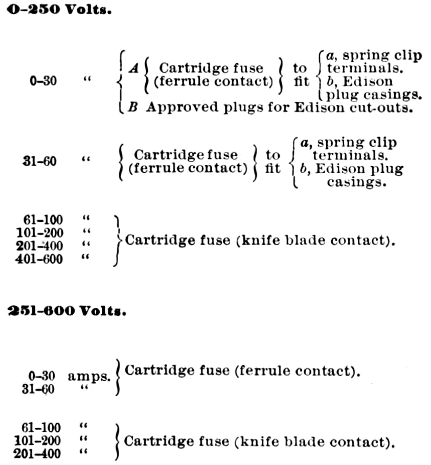
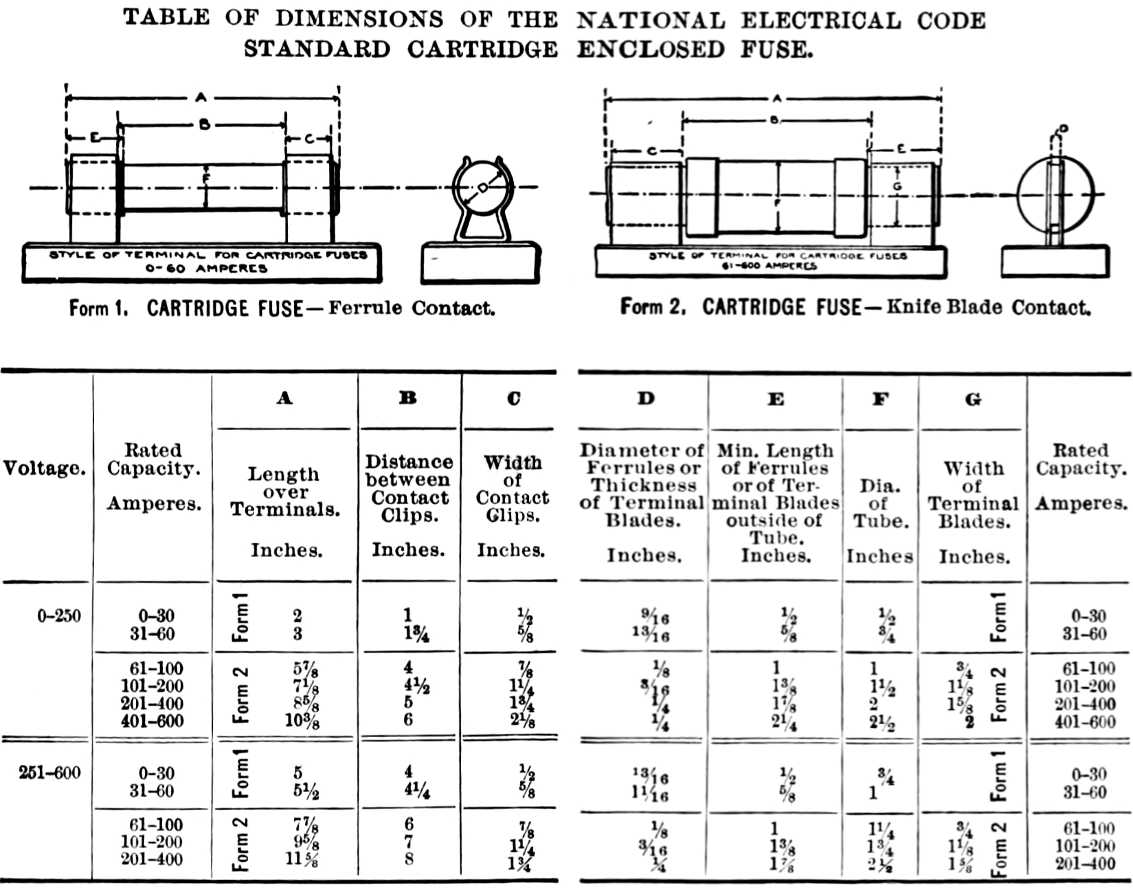
g. Dimensions.—Cartridge enclosed fuses and corresponding cut-out blocks must conform to the dimensions given in the table attached.
TABLE OF DIMENSIONS OF THE NATIONAL ELECTRICAL CODE
STANDARD CARTRIDGE ENCLOSED FUSE
h. Rating.—Fuses must be so constructed that with the surrounding atmosphere at a temperature of 75 degrees Fahrenheit they will carry indefinitely a current 10 per cent greater than that at which they are rated, and at a current 25 per cent greater than the rating, they will open the circuit without reaching a temperature which will injure the fuse tube or terminals of the fuse block. With a current 50 per cent greater than the rating and at room temperature of 75 degrees Fahrenheit, the fuses, starting cold, must blow within the time specified.
| 0-30 amperes, | 30 seconds. |
|---|---|
| 31-60 " | 1 minute. |
| 61-100 " | 2 minutes. |
| 101-200 " | 4 " |
| 201-400 " | 8 " |
| 401-600 " | 10 " |
| i. Marking.—Must be marked, where it will be plainly visible, with the name or trade mark of the maker, the voltage and current for which the fuse is designed, and the words "National Electrical Code Standard." Each fuse must have a label, the color of which must be green for 250-volt fuses and red for 600-volt fuses. |
j. Temperature Rise.—The temperature of the exterior of the fuse enclosure must not rise more than 125 degrees Fahrenheit above that of the surrounding air when the fuse is carrying the current for which it is rated.
k. Test.—Must not hold an arc or throw out melted metal or sufficient flame to ignite easily inflammable material on or near the cut-out, when only one fuse is blown at a time on a short-circuit, on a system having a capacity of 300 K. W. or over, at the voltage for which the fuse is rated.
53 A. Tablet and Panel Boards.
The following minimum distance between bare live metal parts (bus-bars, etc.) must be maintained:—
| Between parts of opposite polarity, except at switches and link fuses. | Between parts of same polarity. | ||
|---|---|---|---|
| When mounted on the same surface. | When held free in the air. | At link fuses. | |
| 0-125 volts | ¾ inch. | ½ inch. | ½ inch. |
| 126-250 volts | 1¼ " | ¾ " | ¾ " |
54. Cut-Out Cabinets.
a. Material.—Cabinets must be substantially constructed of non-combustible, non-absorptive material, or of wood. When wood is used the inside of the cabinet must be completely lined with a non-combustible insulating material. Slate or marble at least one-quarter inch in thickness is strongly recommended for such lining, but, except with metal conduit systems, asbestos board at least one-eighth inch in thickness may be used in dry places if firmly secured by shellac and tacks. With metal conduit systems the lining of either the box or the gutter must be of one-sixteenth inch galvanized, painted or enameled iron, or preferably one-quarter inch slate or marble.
b. Door.—The door must close against a rabbet, so as to be perfectly dust-tight. Strong hinges and a strong hook or catch are required. Glass doors must be glazed with heavy glass, not less than 1-8 inch in thickness, and panes should not exceed 300 square inches in area. A space of at least two inches must be allowed between the fuses and the door. This is necessary to prevent cracking or breaking by the severe blow and intense heat which may be produced under some conditions.
c. Bushings.— Bushings through which wires enter must fit tightly the holes in the box, and must be of approved construction. The wires should completely fill the holes in the bushings, using tape to build up the wire, if necessary, so as to keep out the dust.
54 A. Rosettes.
a. Base.—Current-carrying parts must be mounted on non-combustible, non-absorptive insulating bases. There should be no openings through the rosette base except those for the supporting screws and in the concealed type for the conductors also, and these openings should not be made any larger than necessary. There must be at least 1-4 inch space, measured over the surface, between supporting screws and current-carrying parts. The supporting screws must be so located or countersunk that the flexible cord cannot come in contact with them. Bases for the knob and cleat type must have at least two holes for supporting screws; must be high enough to keep the wires and terminals at least 1-2 inch from the surface to which the rosette is attached, and must have a porcelain lug under each terminal to prevent the rosette from being placed over projections which would reduce the separation to less than 1-2 inch. Bases for the moulding and conduit box types must be high enough to keep the wires and terminals at least 3-8 inch from the surface wired over.
b. Mounting.—Contact pieces and terminals must be secured in position by at least two screws, or made with a square shoulder, or otherwise arranged to prevent turning. The nuts or screw heads on the under side of the base must be countersunk not less than 1-8 inch and covered with a waterproof compound which will not melt below 150 deg. Fahr.
c. Terminals.—Line terminal plates must be at least .07 inch in thickness, and terminal screws must not be smaller than No. 6 standard screw with about 32 threads per inch. Terminal plates for the flexible cord and for fuses must be at least .06 inch in thickness, and the terminal screws must not be smaller than No. 5 standard screw with about 40 threads per inch.
d. Cord Inlet.—The diameter of the cord inlet hole should measure 13-32 inch in order that standard portable cord may be used.
e. Knot Space.—Ample space must be provided for a substantial knot tied in the cord as a whole. All parts of the rosette upon which the knot is likely to bear must be smooth and well rounded.
f. Cover.—When the rosette is made in two parts, the cover must be secured to the base so that it will not work loose. In fused rosettes, the cover must fit closely over the base so as to prevent the accumulation of dust or dirt on the inside, and also to prevent any flash or melted metal from being thrown out when the fuses melt.
g. Markings.—Must be plainly marked where it may readily be seen after the rosette has been installed, with the name or trade mark of the manufacturer, and the rating in amperes and volts. Fuseless rosettes may be rated 3 amperes, 250 volts; fused rosettes, with link fuses, not over 2 amperes, 125 volts.
h. Test.—Fused rosettes must have a fuse in each pole and must operate successfully when short-circuited on the voltage for which they are designed, the test being made with the two fuses in circuit.
55. Sockets.
(For installation rules, see No. 27.)
a. Standard Sizes.—The standard lamp socket must be suitable for use on any voltage not exceeding 250 and with any size lamp up to fifty candle-power. For lamps larger than fifty candlepower a standard keyless socket may be used, or if a key is required, a special socket designed for the current to be used must be made. Any special sockets must follow the general spirit of these specifications.
b. Marking.—The standard socket must be plainly marked 250 v., 50 c. p., and with the manufacturer's name or registered trade mark. Special sockets must be marked with the current and voltage for which they are designed.
c. Shell.—Metal used for shells must be moderately hard, but not hard enough to be brittle or so soft as to be easily dented or knocked out of shape. Brass shells must be at least thirteen one-thousandths of an inch in thickness, and shells of any other material must be thick enough to give the same stiffness and strength as the required thickness of brass.
d. Lining.—The inside of the shells must be lined with insulating material, which must absolutely prevent the shell from becoming a part of the circuit, even though the wires inside the socket should start from their position under the binding screws. The material used for lining must be at least one thirty-second of an inch in thickness, and must be tough and tenacious. It must not be injuriously affected by the heat from the largest lamp permitted in the socket, and must leave water in which it is boiled practically neutral. It must be so firmly secured to the shell that it will not fall out with ordinary handling of the socket. It is preferable to have the lining in one piece.
e. Cap.—Caps, when of sheet brass, must be at least thirteen one-thousandths of an inch in thickness, and when cast or made of other metals must be of equivalent strength. The inlet piece, except for special sockets, must be tapped with a standard one-eighth-inch pipe thread. It must contain sufficient metal for a full, strong thread, and when not in one piece with the cap, must be joined to it in such a way as to give the strength of a single piece. There must be sufficient room in the cap to enable the ordinary wireman to easily and quickly make a knot in the cord and to push it into place in the cap without crowding. All parts of the cap upon which the knot is likely to bear must be smooth and well insulated.
f. Frame and Screws.—The frame which holds the moving parts must be sufficiently heavy to give ample strength and stiffness. Brass pieces containing screw threads must be at least six one-hundredths of an inch in thickness. Binding post screws must not be smaller than No. 5 standard screw with about 40 threads per inch.
g. Spacing.—Points of opposite polarity must everywhere be kept not less than three sixty-fourths of an inch apart, unless separated by a reliable insulation.
h. Connections.—The connecting points for the flexible cord must be made to very securely grip a No. 16 or 18 B. & S. gage conductor. A turned-up lug, arranged so that the cord may be gripped between the screw and the lug in such a way that it cannot possibly come out, is strongly advised.
i. Lamp Holder.—The socket must firmly hold the lamp in place so that it cannot be easily jarred out, and must provide a contact good enough to prevent undue heating with the maximum current allowed. The holding pieces, springs, and the like, if a part of the circuit, must not be sufficiently exposed to allow them to be brought in contact with anything outside of the lamp and socket.
j. Base.—With the exception of the lining, all parts of insulating material inside the shell must be made of porcelain.
k. Key.—The socket key-handle must be of such a material that it will not soften from the heat of a fifty candle-power lamp hanging downwards from the socket in air at 70 degrees Fahrenheit, and must be securely, but not necessarily rigidly, attached to the metal spindle which it is designed to turn.
l. Sealing.—All screws in porcelain pieces, which can be firmly sealed in place, must be so sealed by a waterproof compound which will not melt below 200 degrees Fahrenheit.
m. Putting Together.—The socket as a whole must be so put together that it will not rattle to pieces. Bayonet joints or an equivalent are recommended.
n. Test.—The socket, when slowly turned "on and off" at the rate of about two or three times per minute, while carrying a load of one ampere at 250 volts, must "make and break" the circuit 6,000 times before failing.
o. Keyless Sockets.— Keyless sockets of all kinds must comply with the requirements for key sockets as far as they apply.
p. Sockets of Insulating Material.—Sockets made of porcelain or other insulating material must conform to the above requirements as far as they apply, and all parts must be strong enough to withstand a moderate amount of hard usage without breaking.
q. Inlet Bushing.— When the socket is not attached to a fixture, the threaded inlet must be provided with a strong insulating bushing having a smooth hole at least nine thirty-seconds of an inch in diameter. The edges of the bushing must be rounded and all inside fins removed, so that in no place will the cord be subjected to the cutting or wearing action of a sharp edge.
56. Hanger-Boards for Series Arc Lamps.
a. Hanger-boards must be so constructed that all wires and current-carrying devices thereon will be exposed to view and thoroughly insulated by being mounted on a non-combustible, non-absorptive insulating substance. All switches attached to the same must be so constructed that they shall be automatic in their action, cutting off both poles to the lamp, not stopping between points when started and preventing an arc between points under all circumstances.
57. Arc Lamps.
(For installation rules, see Nos. 19 and 29.)
a. Must be provided with reliable stops to prevent carbons from falling out in case the clamps become loose.
b. All exposed parts must be carefully insulated from the circuit.
c. Must, for constant-current systems, be provided with an approved hand switch, and an automatic switch that will shunt the current around the carbons, should they fail to feed properly. The hand switch to be approved, if placed anywhere except on the lamp itself, must comply with requirements for switches on hanger-boards as laid down in No. 56.
58. Spark Arresters.
(For installation rules, see Nos. 19 c and 29 c.)
a. Spark arresters must so close the upper orifice of the globe that it will be impossible for any sparks, thrown off by the carbons, to escape.
59. Insulating Joints.
(See No. 26 a.)
a. Must be entirely made of material that will resist the action of illuminating gases, and will not give way or soften under the heat of an ordinary gas flame or leak under a moderate pressure. Must be so arranged that a deposit of moisture will not destroy the insulating effect; must show a dielectric strength between gas-pipe attachments sufficient to resist throughout five minutes the application of an electro-motive force of 4000 volts; and must be sufficiently strong to resist the strain to which they are liable to be subjected during installation.
b. Insulating joints having soft rubber in their construction will not be approved.
60. Rheostats.
(For installation rules, see Nos. 4 a and 8 c.)
a. Materials.—Must be made entirely of non-combustible materials except such minor parts as handles, magnet insulation, etc. All segments, lever arms, etc., must be mounted on non-combustible, non-absorptive, insulating material.
b. Construction.—Must have legs which will keep the current-carrying parts at least one inch from the surface on which the rheostat is mounted. The construction throughout must be heavy, rugged, and thoroughly workmanlike.
c. Connections.—Clamps for connecting wires to the terminals must be of a design which will ensure a thoroughly good connection, and must be sufficiently strong and heavy to withstand considerable hard usage. For currents above fifty amperes, lugs firmly screwed or bolted to the terminals, and into which the connecting wires shall be soldered, must be used.
d. Marking.—Must be plainly marked, where it may be readily seen after the device is installed, with the rating and the name of the maker; and the terminals of motor-starting rheostats must be marked to indicate to what part of the circuit each is to be connected, as "line," "armature," and "field."
e. Contacts.—The design of the fixed and movable contacts and the resistance in each section must be such as to secure the least tendency towards arcing and roughening of the contacts, even with careless handling or the presence of dirt. In motor-starting rheostats, the contact at which the circuit is broken by the lever arm when moving from the running to the starting position, must be so designed that there will be no detrimental arcing. The final contact, if any, on which the arm is brought to rest in the starting position must have no electrical connection.
f. No-voltage release.—Motor-starting rheostats must be so designed that the contact arm cannot be left on intermediate segments, and must be provided with an automatic device which will interrupt the supply circuit before the speed of the motor falls to less than one third of its normal value.
g. Overload-release.—Overload-release devices which are inoperative during the process of starting a motor will not be approved, unless other circuit-breakers or fuses are installed in connection with them.
h. Test.—Must, after 100 operations under the most severe normal conditions for which the device is designed, show no serious burning of the contacts or other faults, and the release mechanism of motor-starting rheostats must not be impaired by such a test. Field rheostats, or main-line regulators intended for continuous use, must not be burned out or depreciated by carrying the full normal current on any step for an indefinite period. Regulators intended for intermittent use (such as on electric cranes, elevators, etc.) must be able to carry their rated current on any step for as long a time as the character of the apparatus which they control will permit them to be used continuously.
61. Reactive Coils and Condensers.
a. Reactive coils must be made of non-combustible material, mounted on non-combustible bases and treated, in general, as sources of heat.
b. Condensers must be treated like other apparatus operating with equivalent voltage and currents. They must have non-combustible cases and supports, and must be isolated from all combustible materials and, in general, treated as sources of heat.
62. Transformers.
(For installation rules, see Nos. 11, 13, 13 A and 36.)
a. Must not be placed in any but metallic or other non-combustible cases.
b. Must be constructed to comply with the following tests:—
- Shall be run for eight consecutive hours at full load in watts under conditions of service, and at the end of that time the rise in temperature, as measured by the increase of resistance of the primary coil, shall not exceed 135 degrees Fahrenheit.
- The insulation of transformers when heated shall withstand continuously for five minutes a difference of potential of 10,000 volts (alternating) between primary and secondary coils and between the primary coils and core, and a no-load "run" at double voltage for thirty minutes.
63. Lightning Arresters.
(For installation rules, see No. 5.)
a. Lightning arresters must be of approved construction. (See list of Electrical Fittings.)